Mini Robotic Arm

Why make a Mini Robotic Arm?

I have always been really curious on how an Industrial Robotic Arm is made. Since this module allows students to make any project they would like to, I have decided to make a Mini Robotic Arm.

Prototype

Since I am from the Diploma of Robotics and Mechatronics, I have some knowledge of making a 3D model as well as programming from scratch. However, I have never made an electrical schematic on my own. Therefore, I have decided to make a prototype to test whether my idea would or would not work.
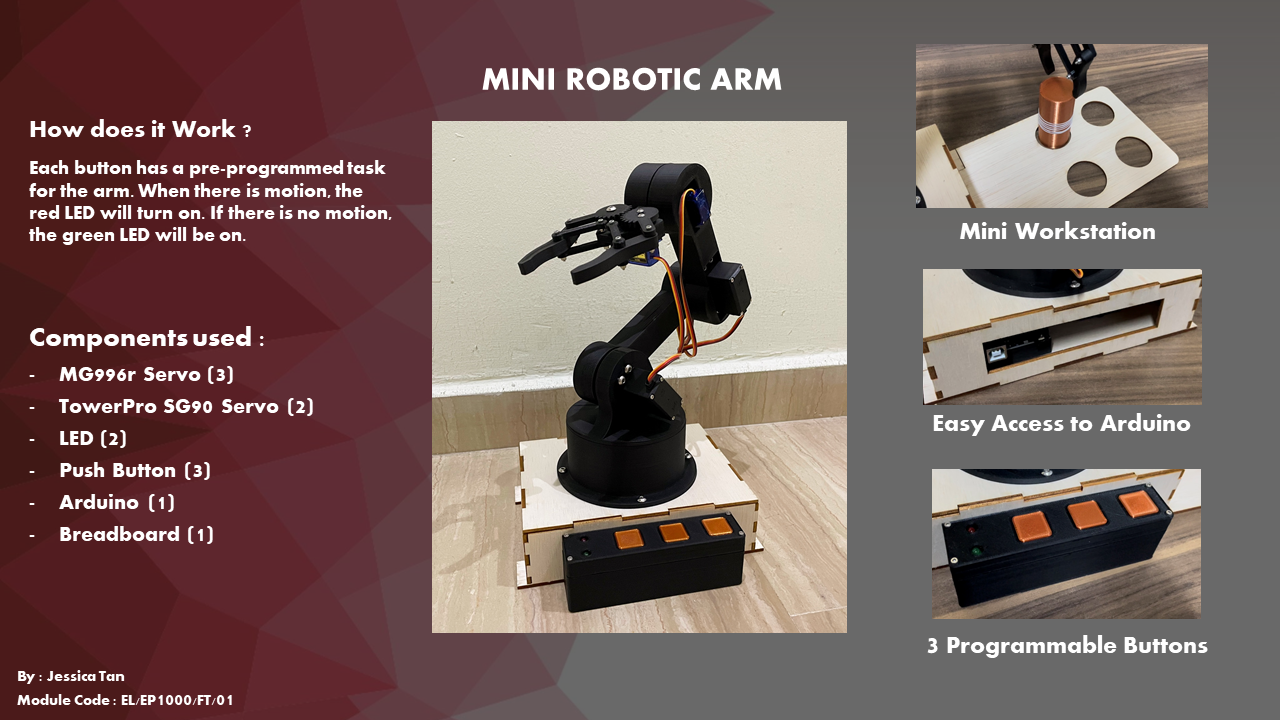
Here's how the 3D model prototype looked like:

Components:

1. Arduino Uno (1)

2. Breadboard (1)

3. TowerPro SG90 Servo Motor (4)

Here's the circuit and code:

I have learnt a lot from making the prototype. E.g. Tolerance value as the 3D printer does not print the exact size I have made in Fusion360, torque of the TowerPro SG90 Servo Motor, as well as designing the circuit all by myself. Now, let's move on to the final version of the Mini Robotic Arm project.

Final Mini Robotic Arm

For the project requirement, I am to have at least a Laser Cut part, 3D Printed part, Input Device and Output Device.

Here's my Concept Sketch:

Laser Cut Part : Large box that contains the Arduino uno and Circuit wiring.

3D Printed Part : Robotic Arm, box that displays the LEDs and Push Buttons and the Object/Part.

Input Device : Push Buttons.

Output Device : LEDs and Servo Motors.

How it'll work:

Since there are 3 Push Buttons, each Push Button will contain a pre-programmed code. The Green LED would always be turned on when none of the Push Buttons are pressed. When any of the Push Button is pressed, the Green LED would turn off and the Red LED would turn on. The pre-programmed code would then be executed.

Bill of Materials:

I decided to use 3 MG996R Servo Motors as the torque is much higher. A higher torque value means that I do not have to worry about the weight the Servo Motor has to carry.

Here's the final 3D Model:

Here's how I designed it:

Robot Base:

Rotating Disk:

1st Arm:

2nd Arm:

Gripper:

Electronic Box:

LEDs and Buttons Holder:

Workstation:

Final Electrical Circuit

For the electrical circuit, I will be using an external power source to power it. This is because I am having 5 servo motors in my circuit. The current drawn from these motors would be really high. The 5V source from the Arduino UNO would not be able to handle it. I have also removed 3 resistors, which was suppose to be connected with the Push Buttons. The reason why I am able to remove the resistors is due to my code. I will be explaining it at the Programming part.

Fabrication

How I'll be fabricating my 3D model parts is by Laser Cutting and 3D Printing.

For Laser Cutting, I would need to import the 2D face of the 3D model, and get the .svg file.

Here's the final .svg files:

For 3D Printing, I would need to slice the 3D model to get the gcode file.

Here's my sliced the parts:

Assembly:

Troubleshooting

After assembling the Mini Robotic Arm, I decided to test out each servo motor individually. The code I used is just to make the servo motor move 180 degrees clockwise, anticlockwise, and then stop. However, I have faced a problem. The servo motor would always reset itself halfway through the program.

The external power source when I was testing the servo motor, was battery pack.

I went on to ask Mr Steven for help, and he suggested me to use a bench power supply or a 6V power adapter as the current flow would be much more stable. Therefore, I went on to use a 6V power adaptor I found at home to test it out. Thankfully, it worked.

Programming

Since there are 3 Push Buttons, I would be using the if-else statement.

Earlier on, I mentioned that no resistors are connected to the Push Buttons. This is because in void_setup(), the pinMode(BUTTON, INPUT_PULLUP); code actually tells the arduino to give some resistance to the Push Buttons. Therefore, I did not use any resistors in my circuit.

Conclusion

Overall, I have learnt a lot after making this Mini Robotic Arm. Although it took a lot of time and effort to make one, I am really happy with the final product. If I had more time, I would try to make the physical circuit wirings neater, as well as improving the codes. I would like to thank Mr Steven for his help and advice. This journey would definitely be a start as I wish to make something more complex in the future!